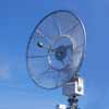
Commercial Terrestrial Microwave Products & Accessories
Our expert team is dedicated to developing innovative solutions that meet the diverse needs of their customers in this field.
Browse our products
Custom, Specialty Feeds, Horns and Systems
Alaris mWave is your first choice for Custom RF Feed Solutions for your most chellenging applications.
Browse our products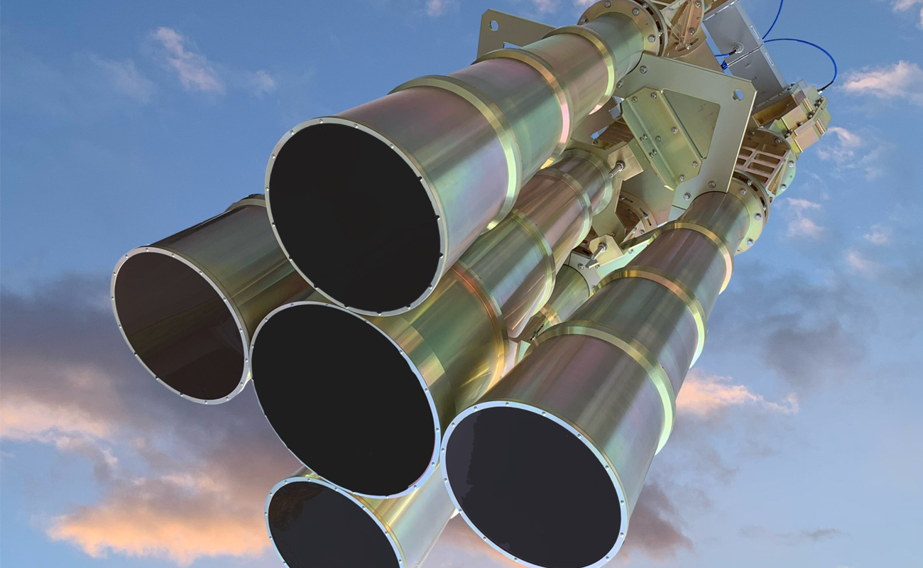
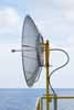
Satellite and Custom Products
Alaris mWave specializes in creating custom satellite products that are designed to meet the unique needs of their clients.
Browse our products